Translate this page into:
A novel “Precision technique” for preoperative planning of posterior tibial slope correction osteotomy
*Corresponding author: Pranjal Sharad Kodkani, Department of Orthopedics, Center for Joint Preservation Surgery: Arthroscopy & Sports Injury, Mumbai, India. pranjalkodkani@gmail.com
-
Received: ,
Accepted: ,
How to cite this article: Kodkani PS. A novel “Precision technique” for preoperative planning of posterior tibial slope correction osteotomy. J Arthrosc Surg Sports Med. 2024;5:51-8. doi: 10.25259/JASSM_13_2024
Abstract
Identification of posterior tibial slope (PTS) and slope correction osteotomies have lately gained importance in various knee surgeries. The preferred surgical methods have been a flexion (opening)/extension (closing) wedge osteotomy at the proximal tibia. Current methods of PTS measurements use the anterior tibial cortical line (ATL), posterior tibial cortical line (PTL), or the anatomical axis of tibia (AAT) on a short lateral view X-ray of the tibia. This can have a high inter and intra-observer variability. Measuring the PTS using the “mechanical axis” has potentially less inter and intra-observer error. However, simply using the difference between pre-operative and planned post-operative PTS measures as the osteotomy correction angle (OCA), with the reference line as “mechanical axis” gives erroneous correction. A novel “Precision technique” is devised to calculate the OCA with least errors using the “mechanical axis” as the reference line. This technique minimizes errors in pre-operative planning. This can further translate into better clinical results due to a reduction in pre-operative planning errors. The principles of this technique can also be used to plan other osteotomies for angular corrections of long bones where the joint line/slope/alignment is to be corrected with reference to the mechanical axis.
Keywords
High tibial osteotomy
Posterior tibial slope
Slope correction osteotomy
Preoperative planning
Errors in osteotomy
Flexion (opening)/extension (closing) wedge osteotomy

INTRODUCTION
Currently, posterior tibial slope (PTS) measurements are done on the medial or lateral tibial plateau[1] using reference lines of the proximal tibia using a short lateral view X-ray of the knee [Figure 1]. However, there is no standardization on the length of the short lateral X-ray or points and levels of the tibia to be considered for reference lines (ATL, PTL, and AAT). Therefore, a high degree of inter and intra-observer variation exists in marking these lines. This leads to significant variation in measurements of PTS [Figure 2a-c].[2-5]
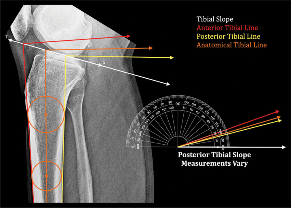
- Posterior tibial slope measurements vary depending on the line of reference. Tibial slope (TS) line – Line joining the anterior and posterior edge of tibial plateau,
 : Anterior tibial line,
  : Posterior tibial line,
  : Anatomical axis. Circles are marked touching the anterior and posterior tibial cortex. Line joining their centers represents the Anatomical Axis of Tibia (AAT).
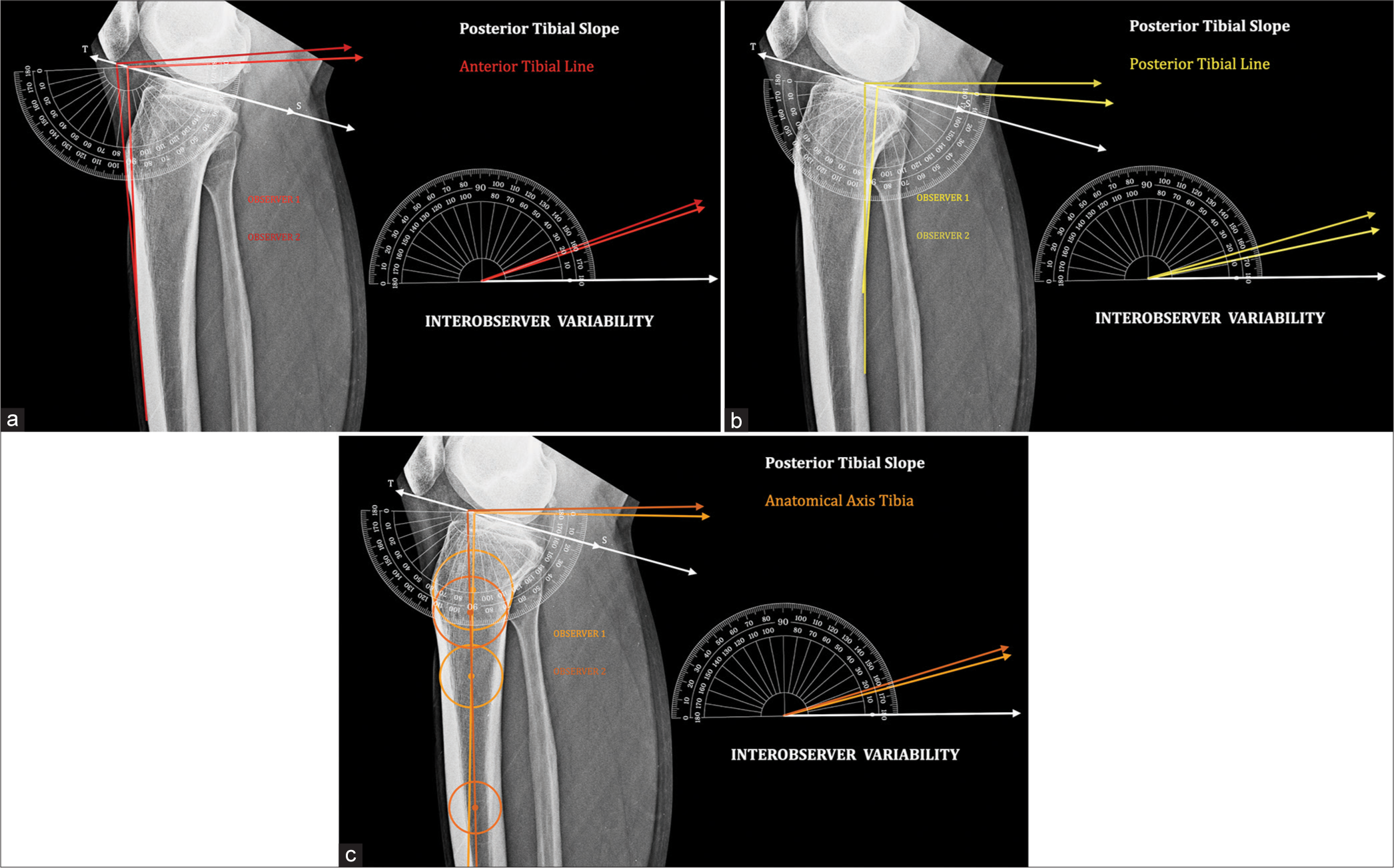
- Interobserver variability: Tibial slope (TS) line – Line joining the anterior and posterior edge of tibial plateau. Posterior tibial slope measured by two observers shows a significant difference and therefore erroneous. (a) Anterior tibial line.
: Observer 1, : Observer 2. (b) Posterior tibial line. : Observer 1, : Observer 2. (c) Anatomical axis tibia. : Observer 1, : Observer 2.The measure of PTS also varies with the reference line considered.[3-5] Demarcating these lines is difficult in the presence of an abnormally shaped tibia in malunion, bowing,[6] and dysplasia.
A way to minimize errors in PTS measurement is to use the “mechanical axis” as a line of reference [Figure 3]. This line extends from the midpoint of the tibial plateau to the midpoint of the tibial plafond at the distal tibia. There is least variability in marking the “mechanical axis.”[5,7,8] PTS measurement, therefore, has the least errors using the “mechanical axis.”
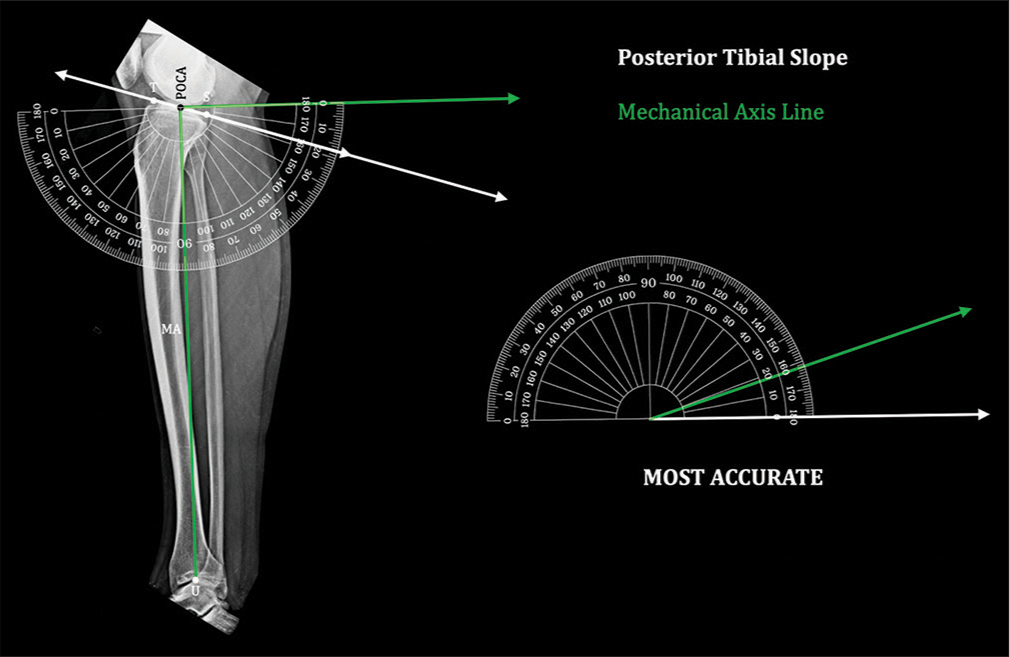
- Posterior tibial slope by “mechanical axis”: Posterior tibial slope measured by this method has standard points of measurement without errors. It is therefore the most accurate method. Tibial slope (TS) line – Line joining the anterior and posterior edge of tibial plateau, Point of calculation of angle (midpoint of the segment ) – POCA, midpoint of tibial plafond at ankle – U, mechanical axis () – MA.
Calculation of angular correction becomes erroneous with the current traditional calculation technique (using a measure of the angular difference between pre- and planned postoperative PTS as the OCA) if applied with the “mechanical axis” [Figure 4a-d]. It can be used without errors when the ACA coincides with the point of calculation of angle (POCA) or with reference lines such as ATL, PTL, or AAT. However, in an opening or closing wedge osteotomy, ACA does not coincide with POCA, resulting in erroneous corrections. Therefore, the current technique cannot be applied using the “mechanical axis” as the reference line.
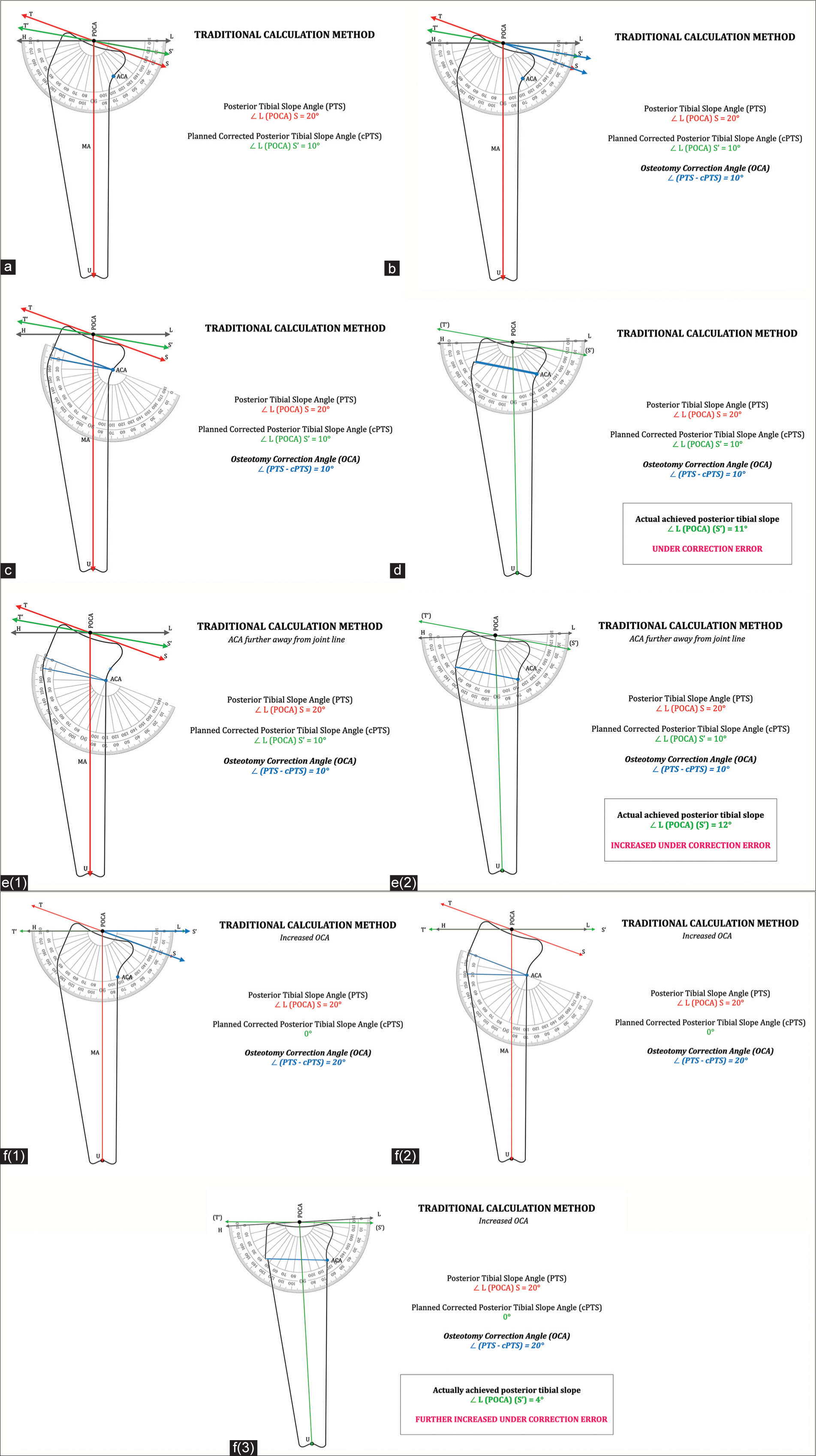
- Traditional calculation method of posterior tibial slope correction: (a) Representative lateral view of tibia. Tibial slope line/segment – TS, Planned postoperative tibial slope – T’S’, Point of calculation of angle (midpoint of tibial plateau) – POCA, Midpoint of tibial plafond at ankle – U, pre-operative mechanical axis ( ) – MA, Horizontal line drawn perpendicular to MA at the POCA – HL, Pre-operative posterior tibial slope angle – PTS, Postoperative planned (corrected) posterior tibial slope angle – cPTS, Axis of correction of angulation – ACA. (b) Osteotomy correction angle (OCA). PTS – cPTS = OCA. (c) Osteotomy correction angle (OCA) is marked at the axis of correction of angulation (ACA) replicating the osteotomy wedge. (d) Osteotomy correction angle wedge is closed. Posterior tibial slope angle achieved is measured ∠ L (POCA) (S’). Actual achieved posterior tibial slope angle is under-corrected and erroneous. (Planned posterior tibial slope – 10°; Achieved posterior tibial slope – 11°). (e) ACA further away from joint line: e(1) Same OCA (10°) marked at new distal ACA. e(2) – OCA wedge is closed. Posterior tibial slope angle is measured ∠ L (POCA) (S’). Actual achieved posterior tibial slope angle is with increased under-correction error (Planned posterior tibial slope – 10°; Achieved posterior tibial slope – 12°). (f) Increased osteotomy correction angle (OCA): f(1) OCA increased (to 20°) to achieve cPTS of 0°. f(2) – OCA is marked at the axis of correction of angulation (ACA) replicating the osteotomy wedge. f(3) – OCA wedge is closed. Posterior tibial slope angle is measured ∠ L (POCA) (S’). Actual achieved posterior tibial slope angle is with further increased under-correction error (Planned posterior tibial slope – 0°; Achieved posterior tibial slope – 4°).
The novel “Precision technique” is devised to avoid errors in the calculation of OCA irrespective of the position of ACA and to minimize observation errors. Principles of this technique can be used for all angular correction osteotomies. However, these principles cannot be applied to short films using lines other than the “mechanical axis” as the line of reference. Using this technique, one can have precise calculations of OCA even in the presence of diaphyseal abnormalities since it avoids diaphyseal points of reference.
THE “PRECISION TECHNIQUE”
A knee-to-ankle full-length lateral view X-ray tibia is taken. Planning should not be done on a short X-ray or a sagittal MRI of the knee [Video 1].[9]
Video 1:
Video 1:This video demonstrates the observational errors in the measurement of posterior tibial slope achieved using anterior tibial line, posterior tibial line, and anatomical axis tibia. The mechanical axis of the tibia is the most reliable method of measuring the posterior tibial slope (PTS) with least errors. In the traditional method of planning, the difference between pre-operative and planned post-operative PTS is considered osteotomy correction angle (OCA). However, if used with the mechanical axis of the tibia as the line of reference, it results in errors of correction achieved. Therefore to measure the PTS without observational errors and to be able to plan the precise OCA pre-operatively, the “Precision technique” is devised. The “Precision technique” relies on the mechanical axis of tibia and position of the axis of correction of angulation (ACA) of osteotomy. Once these are well defined, one can plan the OCA using the technique without any pre-operative planning errors. This can give more precise corrections surgically and possibly more reliable results.Points of importance and abbreviations
Tibial slope line/segment – TS. Planned post-operative tibial slope – T’S’. Point of calculation of angle (midpoint of tibial plateau) – POCA. Midpoint of tibial plafond at ankle – U. Pre-operative mechanical axis ( ) – MA. Planned post-operative mechanical axis – MA’. Pre-operative posterior tibial slope angle – PTS. Post-operative planned (corrected) posterior tibial slope angle – cPTS. Difference in posterior tibial slope angles – dPTS. Anterior proximal tibial angle ∠ T (POCA) U – APTA. Planned post-operative (corrected) anterior proximal tibial angle – cAPTA.
Axis of correction of angulation – ACA
Osteotomy correction angle – OCA
TS is marked considering anterior edge (T) and posterior edge (P) of the tibial plateau in the lateral view.
Mechanical axis (MA) is drawn from POCA to U. Horizontal line (HL) is drawn perpendicular to MA at POCA.
Angle ∠ L (POCA) S is posterior tibial slope angle (PTS). Planned posterior tibial slope (T’S’) is drawn at POCA with respect to HL.
Angle ∠ L (POCA) S’ is planned corrected posterior tibial slope angle (cPTS).
Current traditional calculation method
In the current traditional method of calculation,[10,11] the
difference in angular measurement (dPTS) between pre-operative posterior tibial slope angle (PTS) and planned post-operative corrected posterior tibial slope angle (cPTS) is the osteotomy correction angle (OCA) [Video 1].
dPTS = PTS – cPTS = OCA
However, with angles measured in reference to the “mechanical axis,” this results in an erroneous degree of correction [Figure 4ad]. Error is magnified further as ACA moves more distal to the joint line further away from POCA [Figure 4e1 and e2]. The error is exaggerated as OCA increases [Figure 4f1-f3].
The calculation of OCA with the current traditional technique happens at POCA, whereas the actual implementation of angular change is at ACA of osteotomy, which is away from POCA. An opening or closing wedge osteotomy, therefore, results in an angular change of mechanical axis along with a linear shift of POCA. Due to this dPTS, i.e., PTS – cPTS is not equal to OCA, making the current calculation technique erroneous. Hence, we need the “Precision technique” for the calculation of OCA.
Using the “Precision technique” [Figure 5], the difference in posterior tibial slopes dPTS, i.e., PTS – cPTS is either subtracted (to reduce tibial slope) [Figure 5a] or added (to increase tibial slope) to anterior proximal tibial angle (APTA) to get our new planned post-operative mechanical axis (MA’) drawn at corrected angle cAPTA [Figure 5b].
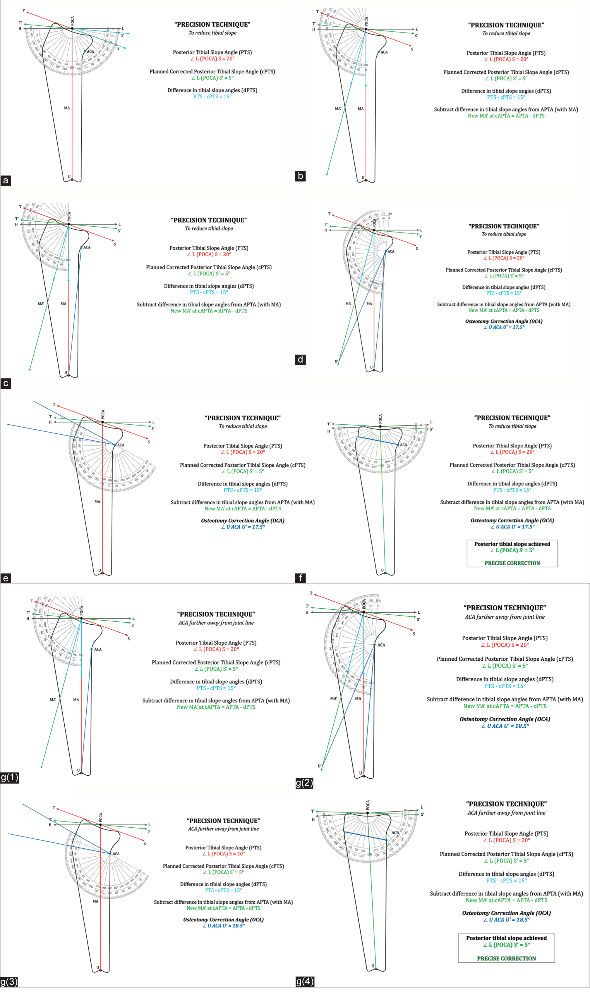
- “Precision technique” of calculating posterior tibial slope correction: Tibial slope line/segment – TS, Planned postoperative tibial slope – T’S’, Point of calculation of angle (midpoint of tibial plateau) – POCA, Midpoint of tibial plafond at ankle – U, Pre-operative mechanical axis ( ) – MA, Planned post-operative mechanical axis – MA’ , Pre-operative posterior tibial slope angle – PTS, Postoperative planned (corrected) posterior tibial slope angle – cPTS, Anterior proximal tibial angle ∠ T (POCA) U – APTA, Planned corrected anterior proximal tibial angle – cAPTA, Axis of correction of angulation – ACA, Osteotomy correction angle – OCA. (a) Difference in posterior tibial slope angles (dPTS). dPTS = PTS – cPTS = ∡ S (POCA) S.’ (b) To reduce tibial slope angle: New mechanical axis MA’ with new anterior proximal tibial angle (cAPTA) is marked at POCA by subtracting dPTS from anterior proximal tibial angle (APTA). MA’ at ∡ cAPTA = APTA – dPTS. (c) Draw a line segment from ACA to U. (d) Extend an arc of radius onto the new mechanical axis MA’ to intersect at point U’. This measure of angle ∡ U ACA U’ is the final precise OCA. (e) OCA is marked at the axis of correction of angulation (ACA) replicating the osteotomy wedge. (f) OCA wedge is closed. Posterior tibial slope angle is measured ∠ L (POCA) S. Posterior tibial slope achieved is precisely same as the planned corrected posterior slope (cPTS) of 5°. (g) ACA further away from joint line: g(1) Draw a line segment from ACA to U. g(2) Extend an arc of radius onto the new mechanical axis MA’ to intersect at point U’. This measure of angle ∡ U ACA U’ is the final precise OCA. Note that the measure of OCA changes as the position of ACA changes. g(3) OCA is marked at axis of correction of angulation (ACA) replicating the osteotomy wedge. g(4) OCA wedge is closed. Posterior tibial slope angle is measured ∠ L (POCA) S. Posterior tibial slope achieved is precisely same as the planned corrected posterior tibial slope (cPTS) of 5°.
To reduce the tibial slope angle
MA’ at cAPTA = APTA – dPTS
To increase the tibial slope angle
MA’ at cAPTA = APTA + dPTS
A line segment is drawn from ACA to U [Figure 5c].
Extend an arc of radius onto the new mechanical axis MA’ to intersect at point U’.
Measure of angle ∡ U ACA U’ is the final precise OCA
Note that OCA is not equal to dPTS as in the current traditional technique. OCA value also changes with the position of ACA [Figure 5d].
Replicating this OCA at ACA for simulating the closing wedge osteotomy confirms the final achieved post-operative tibial slope to be precise [Figure 5e and f].
To achieve the same precise degree of angular correction, the OCA increases
As ACA moves more distal to (away from) joint line [Figure 5g(1-4)]
OR moves closer to point U.
Wider applications of the “Precision technique”
The same principles are applicable to other angular correction osteotomies where planning is for altering joint line/slope/limb alignment using the mechanical axis.
DISCUSSION
Tibial slope correction osteotomies need to be planned appropriately to get precise postoperative corrections. Inaccurate corrections can result in compromised outcomes. It is therefore essential to have precise preoperative planning and calculation of OCA, as errors in planning can get further compounded during surgical execution.
The ‘mechanical axis’ of tibia is the most reliable reference line for measurement of tibial slope with least observer error. However, the traditional method of calculating OCA cannot be applied with this reference line as it gives erroneous results. The “Precision technique” is therefore essential to get accuracy in calculations.
This technique obviates the errors of traditional preoperative planning and gives precise calculation of OCA where a slope change by an angular correction osteotomy is to be planned. The “Precision technique” demonstrates how the OCA varies with the position of ACA of the osteotomy. This finding needs to be considered and care should be taken to avoid altering the ACA intraoperatively while performing angular correction osteotomies.
The principles of this technique can be extended to wider applications for other angular correction osteotomies where the ‘mechanical axis’ is the line of reference and the ACA is well defined.
CONCLUSION
“Precision technique” of pre-operative planning is a reliable and reproducible technique with least observer errors. It can be effectively used for precise calculation of the OCA, where a tibial slope correction osteotomy is planned.
Ethical approval
Institutional Review Board approval is not required.
Declaration of patient consent
Patient’s consent is not required as there are no patients in this study.
Conflicts of interest
There are no conflicts of interest.
Use of artificial intelligence (AI)-assisted technology for manuscript preparation
The authors confirm that there was no use of artificial intelligence (AI)-assisted technology for assisting in the writing or editing of the manuscript and no images were manipulated using AI.
Financial support and sponsorship
Nil.
References
- Variations in medial and lateral slope and medial proximal tibial angle. Knee Surg Sports Traumatol Arthrosc. 2021;29:939-46.
- [CrossRef] [PubMed] [Google Scholar]
- Posterior tibial slope measurements based on the full-length tibial anatomic axis are significantly increased compared to those based on the half-length tibial anatomic axis. Knee Surg Sports Traumatol Arthrosc. 2022;30:1362-8.
- [CrossRef] [PubMed] [Google Scholar]
- Evaluation des méthodes de mesure radiographique de la pente tibiale. Analyse de 83 genoux témoins [Evaluation of methods for radiographic measurement of the tibial slope, A study of 83 healthy knees] Rev Chir Orthop Reparatrice Appar Mot. 1996;82:195-200.
- [Google Scholar]
- Can the tibial slope be measured on lateral knee radiographs? Knee Surg Sports Traumatol Arthrosc. 2014;22:3163-7.
- [CrossRef] [PubMed] [Google Scholar]
- Posterior tibial slope measurements using the anatomic axis are significantly increased compared with those that use the mechanical axis. Arthroscopy. 2021;37:243-9.
- [CrossRef] [PubMed] [Google Scholar]
- Effect of anterior tibial bowing on measurement of posterior tibial slope on conventional X-rays. Arch Orthop Trauma Surg. 2023;143:2959-64.
- [CrossRef] [PubMed] [Google Scholar]
- Inter-observer variability and its correlation to experience in measurement of lower limb mechanical axis on long leg radiographs. J Clin Orthop Trauma. 2016;7:260-4.
- [CrossRef] [PubMed] [Google Scholar]
- Reliability of lower limb frontal plane alignment measurements using plain radiographs and digitized images. J Knee Surg. 2004;17:203-10.
- [CrossRef] [PubMed] [Google Scholar]
- Novel measurement technique of the tibial slope on conventional MRI. Clin Orthop Relat Res. 2009;467:2066-72.
- [CrossRef] [PubMed] [Google Scholar]
- Anterior closing wedge osteotomy for failed anterior cruciate ligament reconstruction: State of the art. J Am Acad Orthop Surg Glob Res Rev. 2022;6:e2200044.
- [CrossRef] [PubMed] [Google Scholar]